DSP profile example
DSP profile example
When we designed the Beocreate 4 channel amplifier and the DAC+ DSP, we decided that we want to give the user the possibility to use the full power of the Digital Signal Processor (DSP) that’s on this board. Most DSPs use a fixed DSP flow and the user can only adjust parameters (e.g. filter frequencies). With our products, you can implement whatever is possible with the DSP.
You can do two things: Just use a DSP profile provided by us and adjust some of the settings via the HiFiBerryOS GUI or design your own DSP profile. Designing your own DSP profile comes at a cost: You need to learn a lot about DSPs and use specific DSP programming tools to create your own DSP programs. If you didn’t do this before, you are probably overwhelmed by all the options of SigmaStudio. We don’t recommend to start from scratch, but use a profile provided by us and modify it.
With this article, we will show you one profile and explain a bit how it works. This should help you to modify it for your specific application.
Let’s have a look:
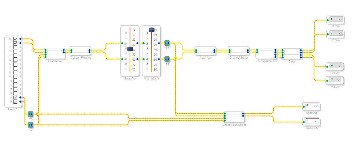
That doesn’t look too complex – right? You see inputs on the left and outputs on the right. Inputs 0/1 are the stereo data from the Raspberry PI, inputs 14/15 data from the Toslink input. On the right side you see output channels 0/1/16/17 that map to the 4 channels on the Beocreate 4-channel amplifier. On the DAC+ DSP, only 0/1 are uses as it inlcudes only a stereo DAC. Also some signals are routed to the TOSLink output.
And there are lots of blocks in between. What do they do? The easiest thing to understand is the volume control. There are two of these to implement a “Volume limit” feature. The “MasterLimit” control won’t be available to apllications. It allows you to set the maximum volume, while the MasterVol can be adjusted by the application.
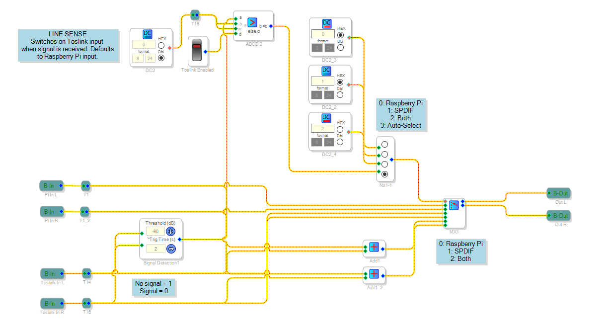
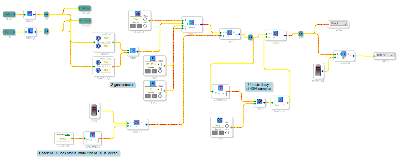
The other blocks are a bit more complex, let’s start with the “LineSense” block. This one detects if there is a signal coming in on TOSLink input. Depending on the switch position of NX1-1, it will select the Raspberry Pi, TOSLink or both as the active audio source.
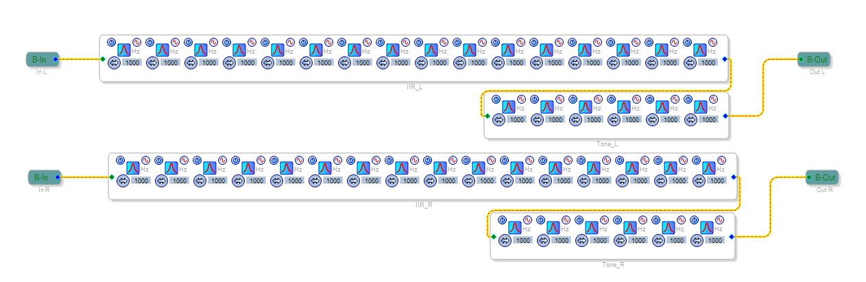
Next is the “Cutoms Filtering” block. It consists of a lot of filter blocks that can implement quite complex equalisation tasks. In their default setting they just pass the signal without modifications, but they can be used later.
Auto-Mute is a block that makes sure that the output stage is muted if no audio is playing. The signal will be detected using signal detectors and status bits of the SPDIF input. If the system has been muted and a new signal is detected, there will be a delay before the output will be unmuted. This helps against plop-sounds.
The of the MUTE signal is handled by GPIO13 on the right side. As the MUTE signal has to be inverted on the DAC+ DSP but not on the Beocreate 4CA, there is another switch that allows to implement this.
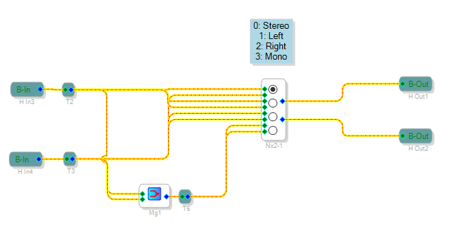
The Channel select block allows to configure the system in Stereo (default), left, right or Mono mode:
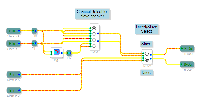
The Direct/Slave select block allows to select what signal is sent to the SPDIF output. This can be used to daisy-chain multiple boards.
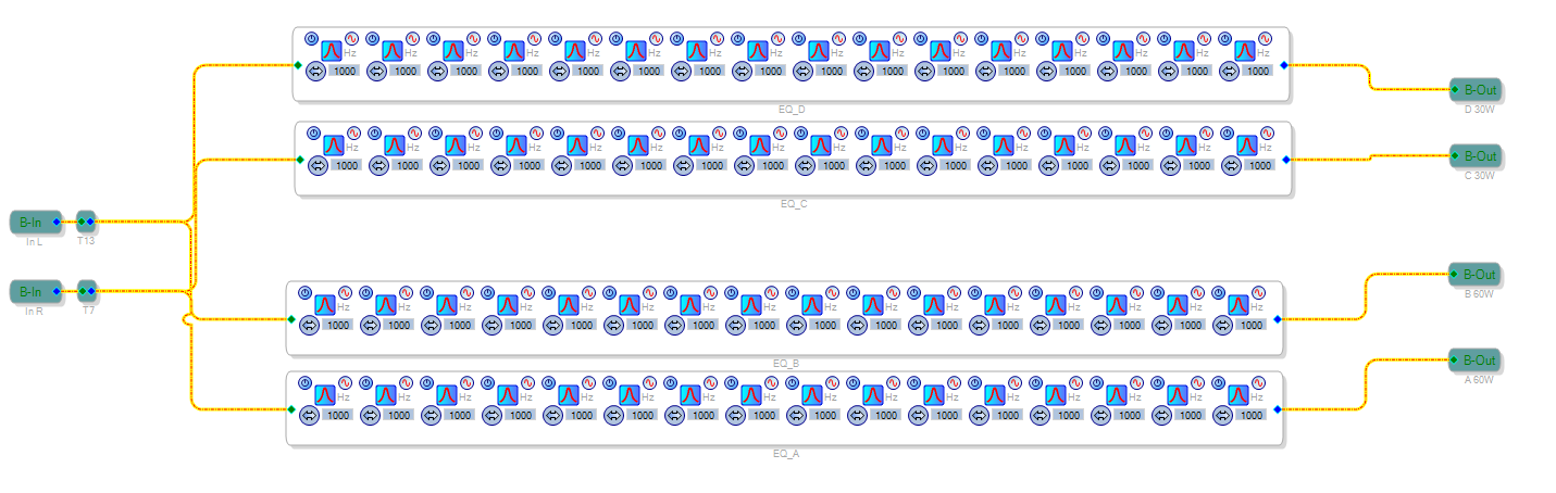
To implement multi-way speakers you want to use different filters for each channel. This is implemented in the “Speaker EQ” block. As before, the default configuration of the filters just passes the signal without modifications:
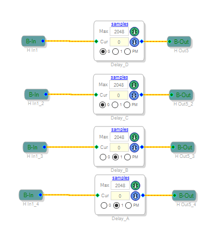
Last thing is a simple “delay” block that allows you to add custom delays to each channel: