Blog
Electronics Design and 3D Modelling: Two Sides of the Same Coin
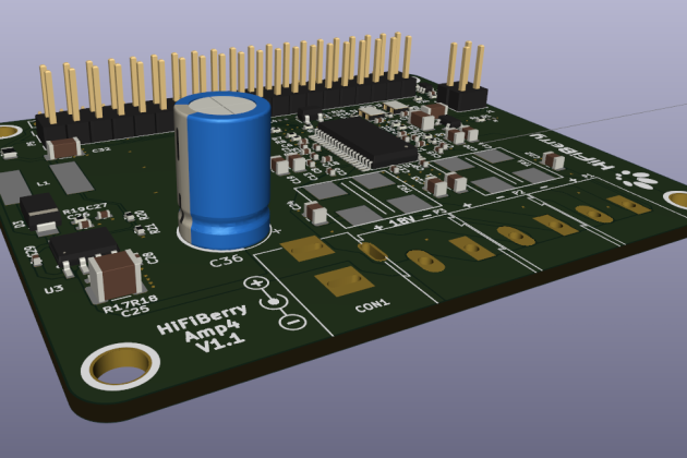
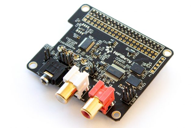
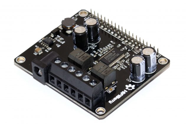
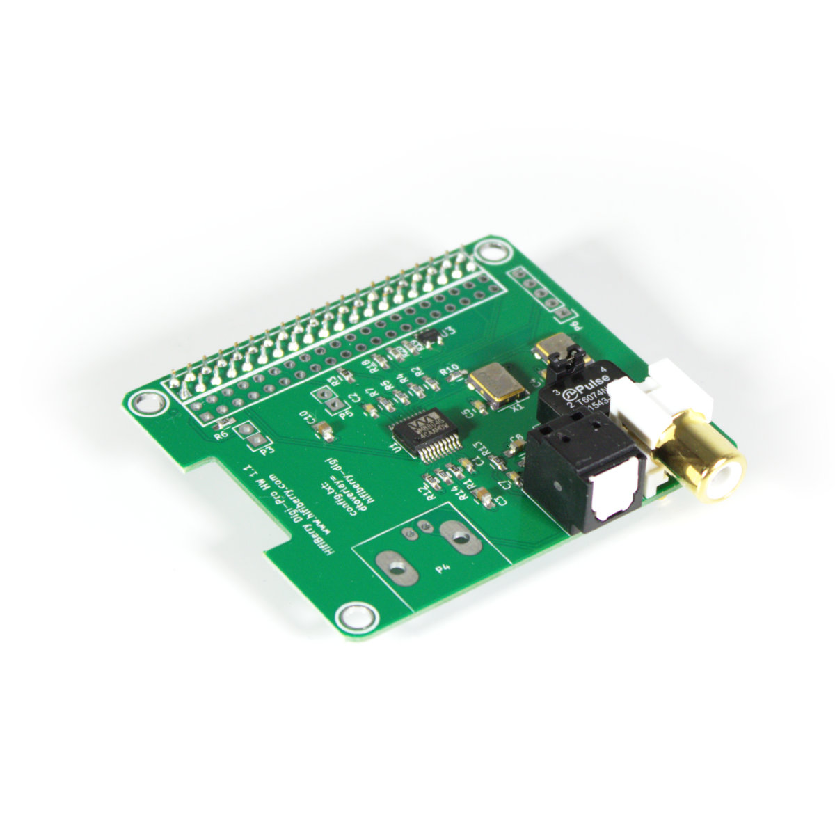
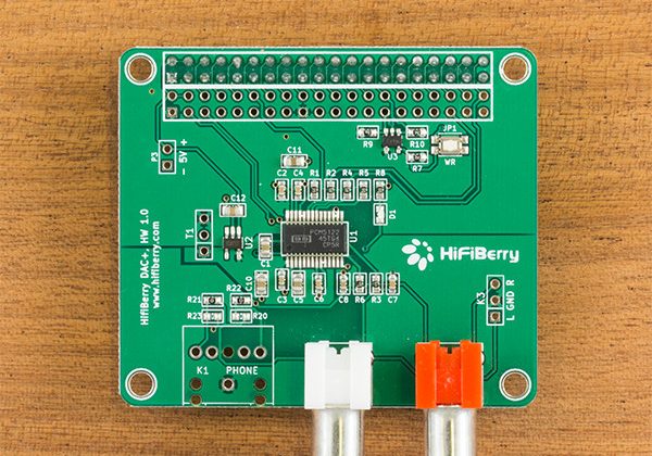
When people think about custom electronics design, they often imagine schematics, PCB layouts, and component selection. What they don’t always picture is a 3D model sitting next to the circuit board design — yet at HiFiBerry, these two disciplines are inseparable. We don’t design custom PCBs in isolation. We design them for a purpose, for a product, for a physical space. And that means understanding the full picture from day one.
PCBs Don’t Float in Mid-Air
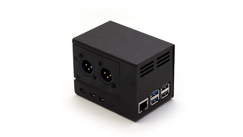
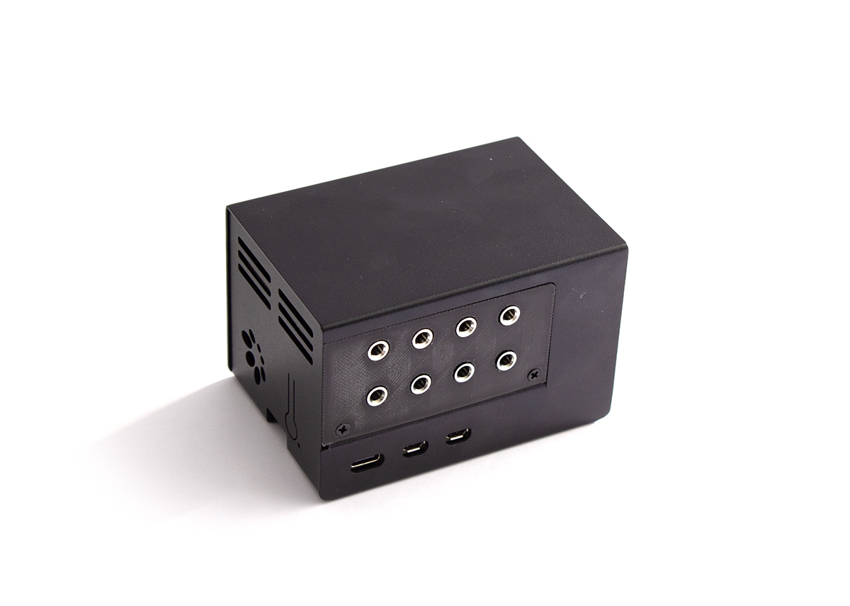
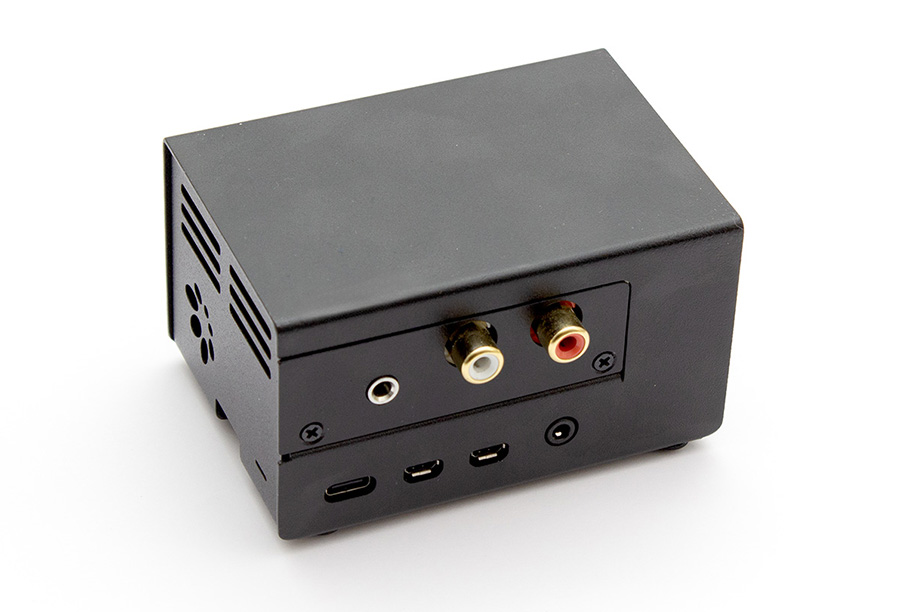
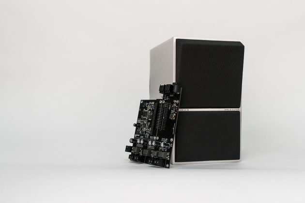
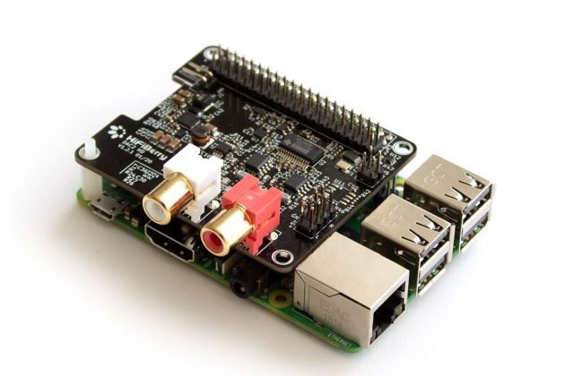
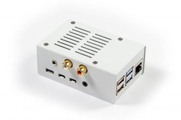
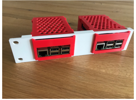
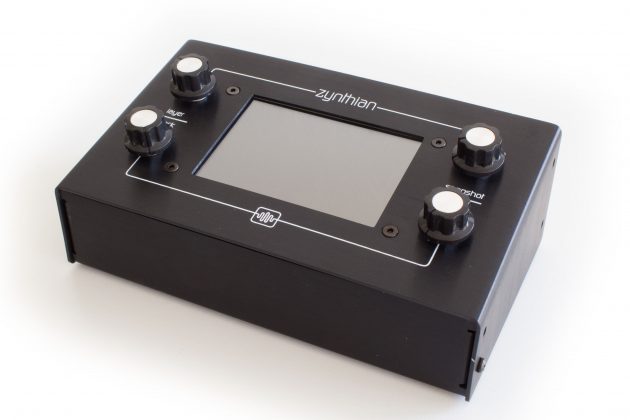
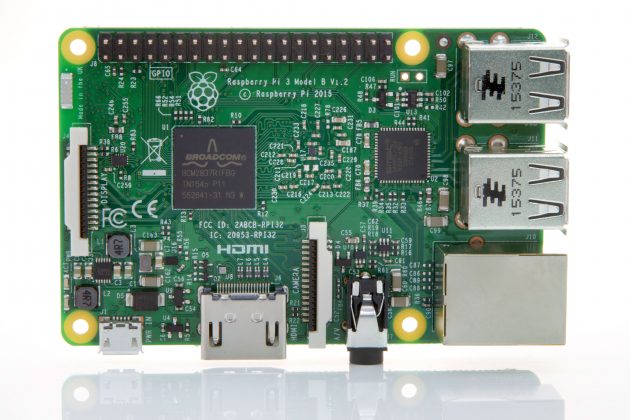
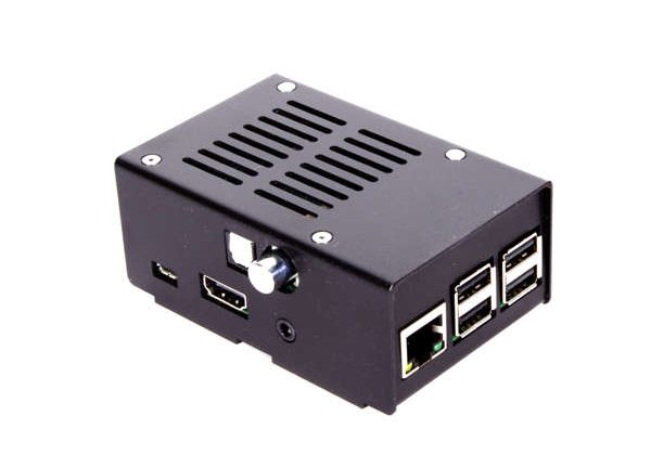
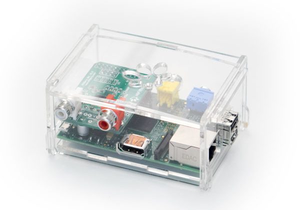
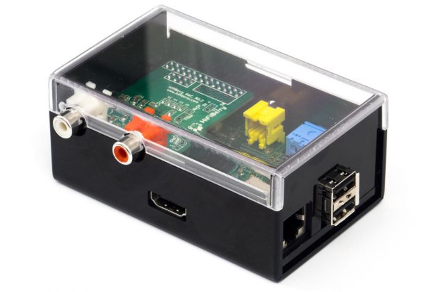
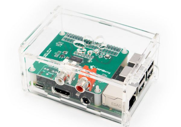
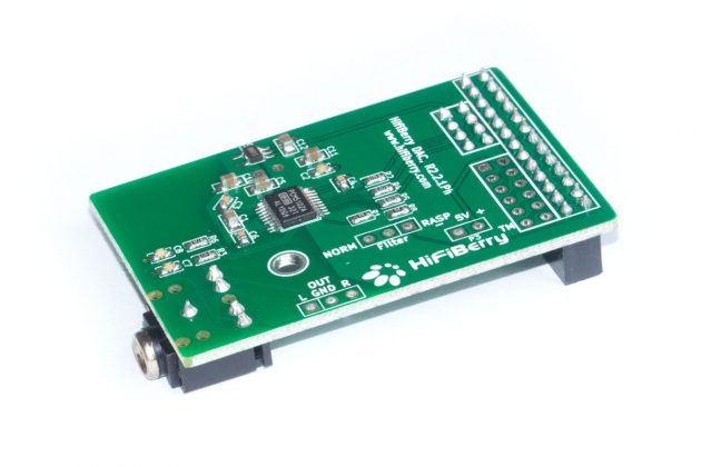
A printed circuit board doesn’t exist in a vacuum. It sits inside an enclosure, mounts to a chassis, connects to ports that need to align with cutouts, and coexists with other boards, cables, and mechanical parts. A few millimetres of error in placement can mean a connector that doesn’t reach, a board that doesn’t fit, or an expensive respin.
This is why we treat electronics design as an inherently spatial problem, not just an electrical one. Before we route a single trace, we want to know where the board will live. What are the physical constraints? How tall can components be? Where are the mounting holes? What are the cutouts for connectors? Where does the heat need to go?
Without answers to these questions, PCB design is little more than educated guesswork.
Why We Ask for 3D Models
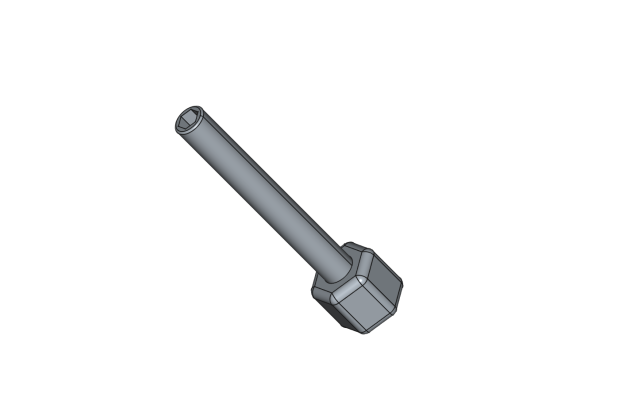
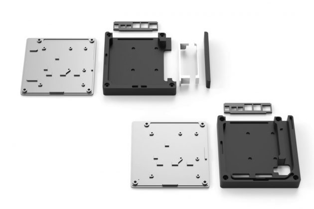
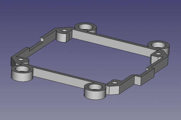
If you’re coming to us with a custom board project, one of the first things we’ll ask for is a 3D model of your enclosure or system — ideally in STEP format. This isn’t a bureaucratic formality. It directly shapes how we approach your design.
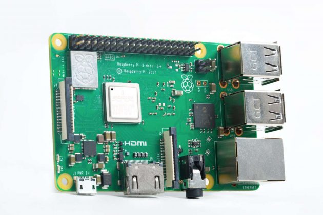
When we have a STEP file of your enclosure, we can import it directly into our PCB design environment and work within your physical constraints from the very beginning. Connector positions are placed so they align with your cutouts. Board outlines are matched to your mechanical tolerances. Component heights are checked against your lid clearance. We can verify fit before a single prototype is manufactured.
This matters more than most people expect. Enclosures and PCBs are typically designed by different teams, sometimes in different companies, often on different timelines. Without a shared 3D reference, small misalignments accumulate. With one, the whole team is working from the same source of truth.
A Better Conversation with Your Customer
Integrating 3D models into the electronics design workflow does something else that’s easy to overlook: it makes the design tangible for everyone involved.
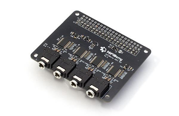
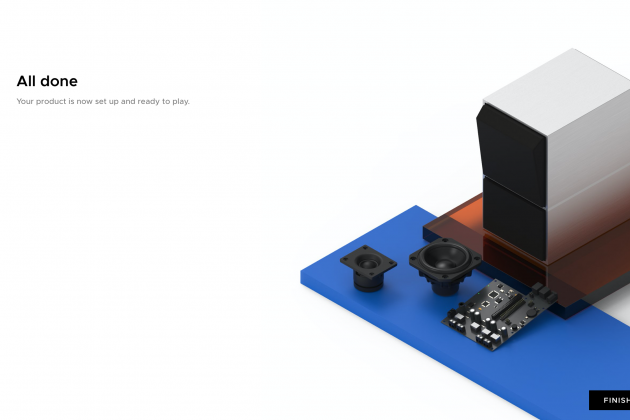
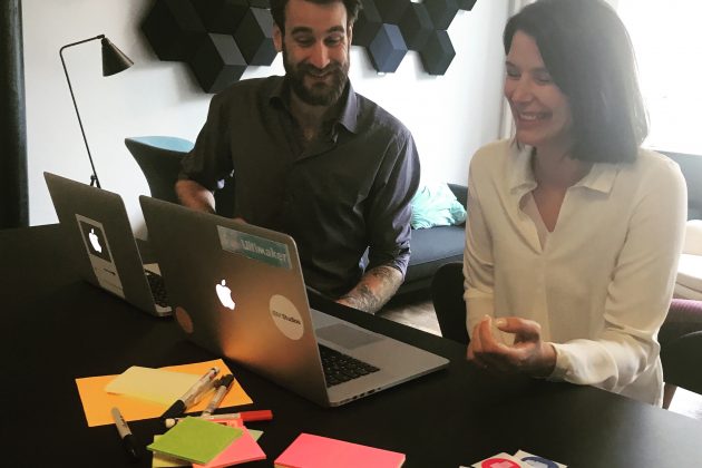
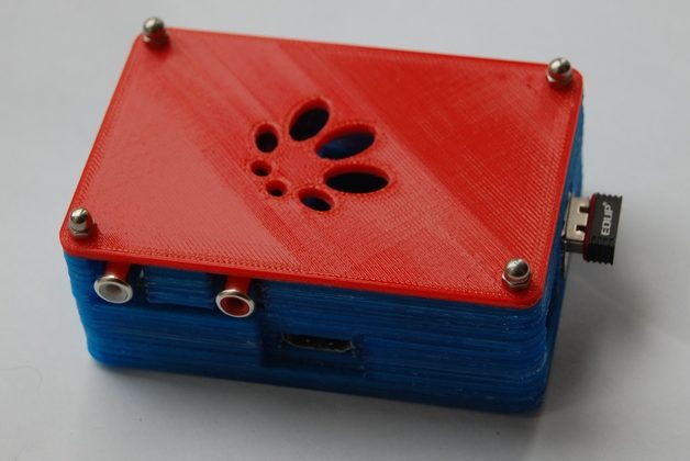
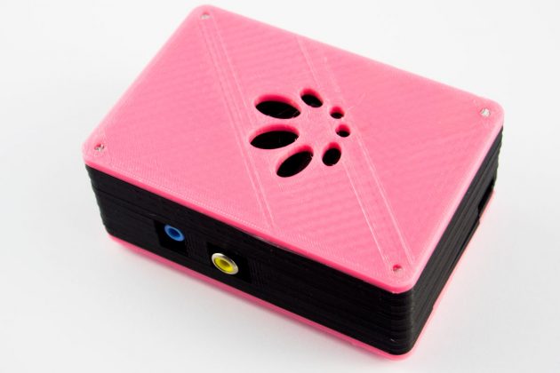
When you can render a board inside its enclosure — showing how it sits, what it connects to, how the ports line up — it becomes immediately understandable to stakeholders who don’t read schematics. Mechanical engineers, product managers, and customers can all look at the same model and give meaningful feedback early in the process.
This is particularly valuable when there are trade-offs to discuss. Should the USB port go on the left or the right? Can the board be shifted 5 mm to make room for the antenna? Is there space for a second mounting hole? These conversations are much more productive when everyone is looking at a 3D render rather than a 2D layout.
Catching these issues early — in software, before any hardware exists — is always cheaper, faster, and less stressful than discovering them on the bench with a prototype in hand.
The Thermal Dimension
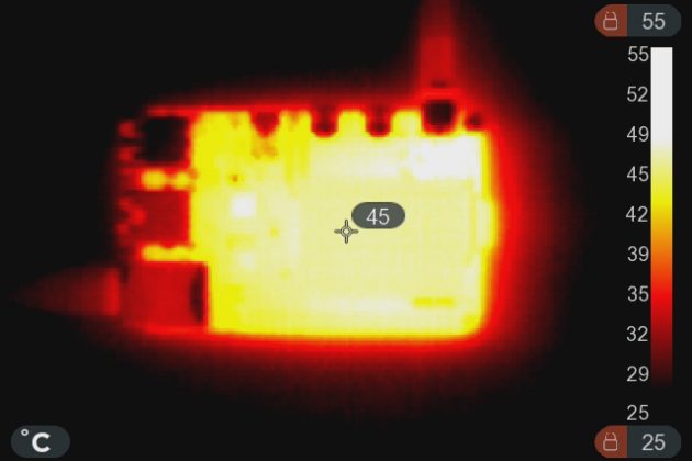
3D integration also pays dividends in thermal design, which is often an afterthought until it becomes a crisis.
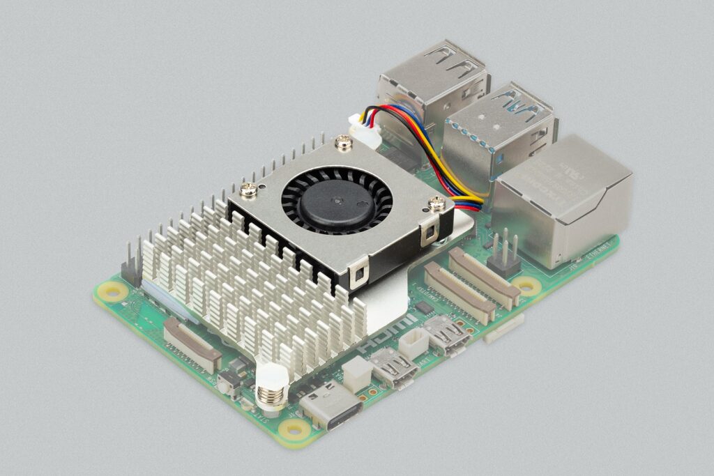
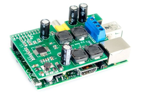
Heat flows through physics, not through wishful thinking. A high-power component placed near a heat-sensitive part of the enclosure, or in a region with poor airflow, will cause problems regardless of how elegant the circuit design is. A component that runs hot needs a thermal path — whether that’s a heatsink, a copper pour, a thermal pad to the chassis, or simply adequate spacing from its neighbours.
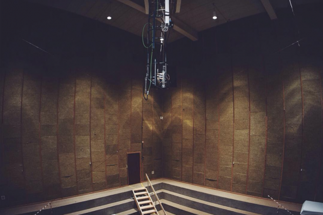
When we have the full 3D picture, we can reason about these things properly. Where is the airflow? Is there a nearby metal wall that can act as a heat spreader? Is the power regulator positioned near a vent, or buried in a corner? These questions can be answered in the design phase — not discovered during stress testing.
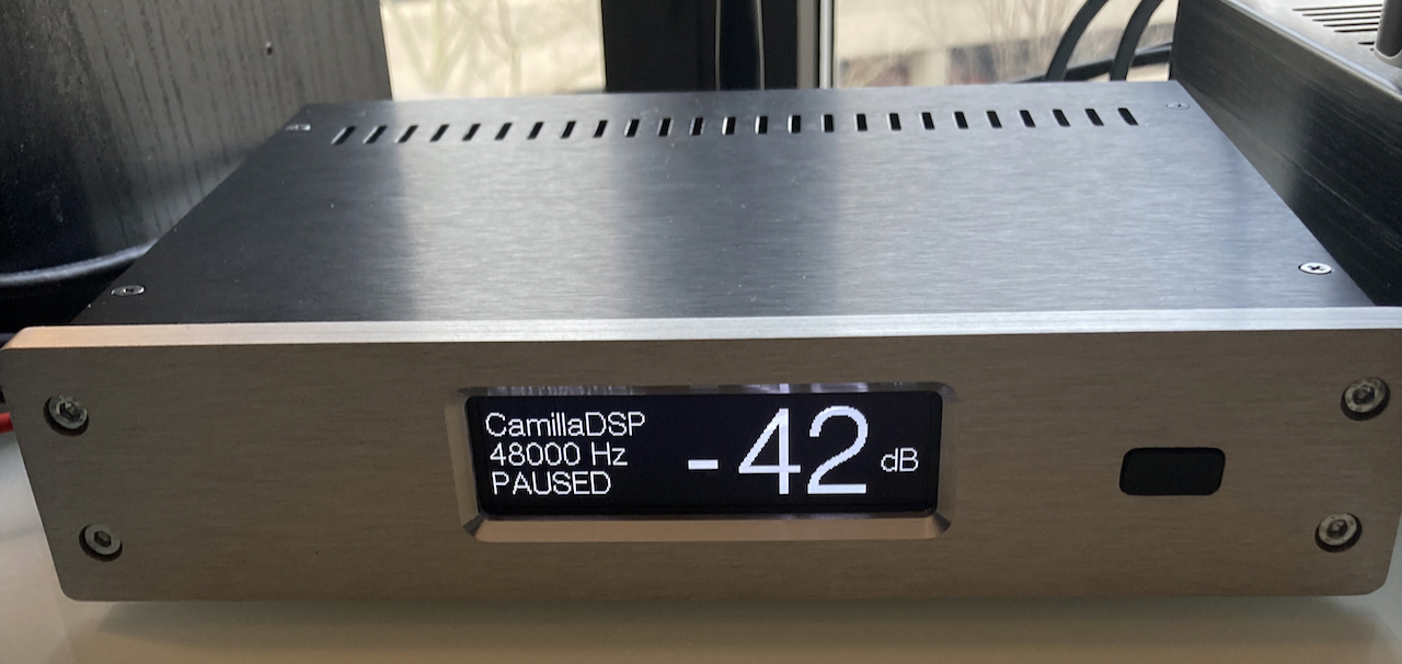
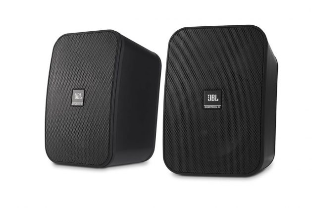
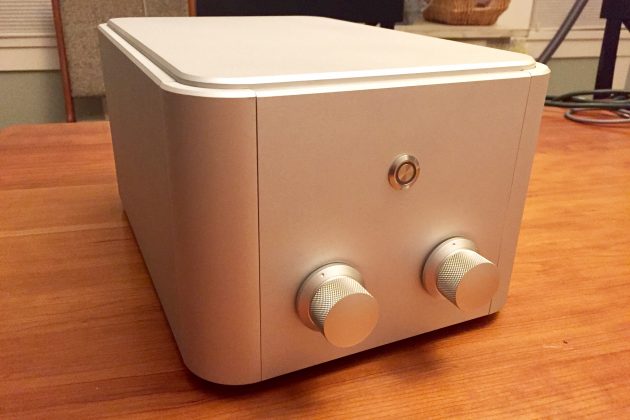
For embedded systems in sealed aluminium enclosures in particular, thermal design can be the difference between a reliable product and one that throttles or fails in the field. Integrating the 3D model early means thermal considerations are baked into the layout, not bolted on afterwards.
A Word of Caution: Models Aren’t Reality
All of this said, there’s an important caveat that we never lose sight of: 3D models are representations, not guarantees.
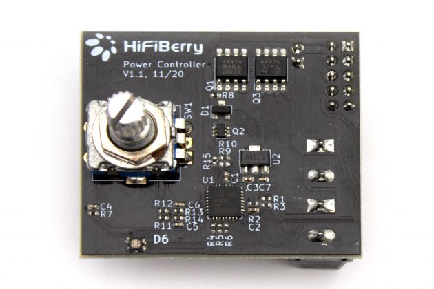
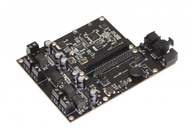
Component models — the 3D bodies attached to footprints in your PCB library — vary significantly in quality. Some are precise, manufacturer-supplied models accurate to the tenth of a millimetre. Others are approximations, sometimes created by third parties, sometimes simplified or slightly off-spec. An integrated design that looks perfect in software may still have a connector that sits a fraction too high, or a board edge that’s a hair too wide.
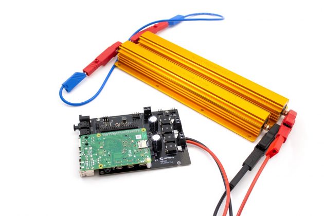
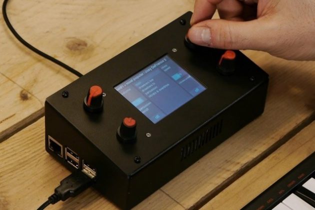
This is why physical validation is non-negotiable before any product goes into mass production. No matter how thorough the 3D integration, no matter how careful the modelling, a real prototype with real components needs to be built, fitted into the real enclosure, and verified by hand. Connectors need to be checked against cutouts. Heights need to be measured. Thermals need to be tested under load.
The 3D workflow dramatically reduces the risk of surprises at this stage. But it doesn’t eliminate the need for the stage itself.
The Takeaway
Good electronics design isn’t just about the circuit. It’s about the whole system — where the board lives, how it fits, how it connects, and how it behaves under real-world conditions. Integrating 3D modelling into the PCB design process is one of the most effective ways to catch problems early, improve collaboration, and deliver a product that works first time.
If you’re planning a custom board project, share your enclosure models with us. The earlier we have them, the better the outcome for everyone.
March 27, 2026